SMD Inductor Marking: Codes 100, 4R7 and R47 Explained
How to read the code on an SMD power inductor or chip inductor: three digits in µH, R as the decimal point, N for nanohenries, ferrite beads rated in ohms. How to tell one from a resistor, how to test it and why inductance alone is not enough for a replacement.
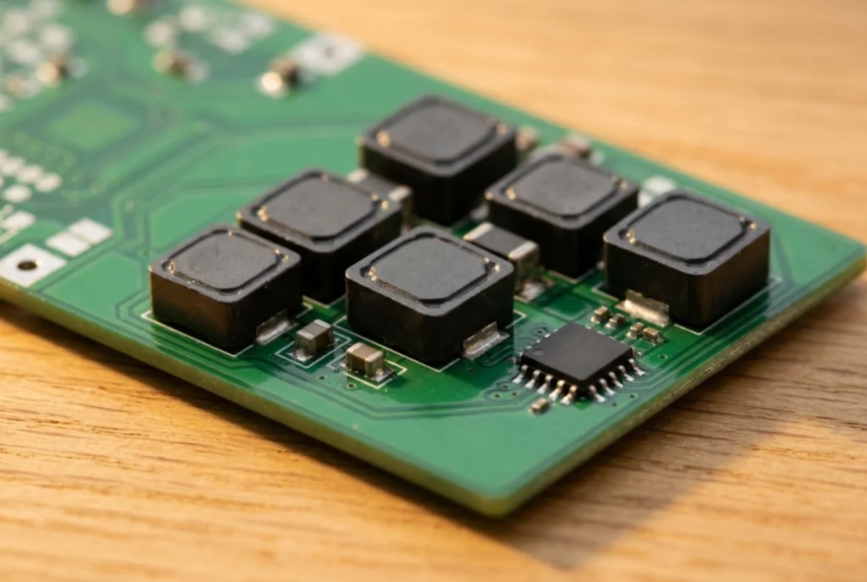
On a repair bench you meet inductors in three forms: a power inductor in a DC-DC converter next to the PMIC, a tiny chip coil in an RF path, and a ferrite bead sitting in a supply rail. Their marking is either three characters or nothing at all. Here is how to read what is printed, and what to do when the part is blank.
Types of SMD inductors
Multilayer chip inductors
They look like any chip capacitor or resistor — a small block with metal end caps — and use the same case sizes: 0402, 0603, 0805, 1206. Values run from a few nanohenries to a few microhenries. Most of them carry no marking at all: some manufacturers even offer “no marking” as an ordering option, and the smallest parts may only get an orientation dot.
Wirewound on a ceramic core
Same footprints, but with real wire inside. You find them in Wi-Fi, Bluetooth and cellular front ends because of their high Q. Usually unmarked as well.
Power inductors
Square or round parts from about 2×2 mm up to 12×12 mm and larger: unshielded drum cores (you can see the winding), shielded types (the winding is enclosed in a ferrite or magnetic sleeve) and moulded composite parts. These are the ones that normally show a value code on top.
Ferrite beads
They look like a 0402–1206 chip, but they are noise absorbers rather than energy-storage inductors. Datasheets rate them by impedance in ohms at 100 MHz, not by inductance — Murata BLM18KG471, for example, is 470 Ω at 100 MHz. At DC a bead is almost a short.
Three-digit code in microhenries
The code works like a resistor code, but the unit is the microhenry (µH): the first two digits are significant, the third is the number of zeros to add.
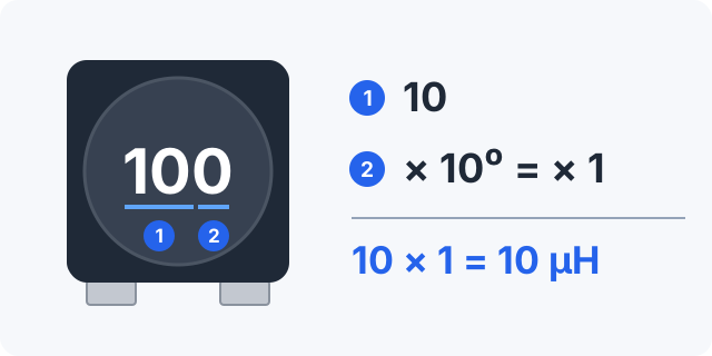
100 means 10 µH, not 100.| Code | Calculation | Inductance |
|---|---|---|
100 | 10 × 1 | 10 µH |
220 | 22 × 1 | 22 µH |
470 | 47 × 1 | 47 µH |
101 | 10 × 10 | 100 µH |
331 | 33 × 10 | 330 µH |
102 | 10 × 100 | 1000 µH = 1 mH |
The classic mistake is reading 100 as one hundred. The final zero is the multiplier, so it is a 10 µH part; 470 is 47 µH.
R as the decimal point
Values below 10 µH use the letter R in place of the decimal point: 4R7 = 4.7 µH, 2R2 = 2.2 µH, 1R0 = 1.0 µH. A leading R means less than one: R47 = 0.47 µH, R10 = 0.1 µH (100 nH).
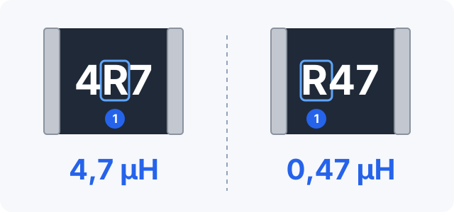
4R7 = 4.7 µH, R47 = 0.47 µH.Resistors use the same notation (4R7 = 4.7 Ω), so the code alone does not tell you what the part is. Look at the body and its surroundings: a converter inductor is a large square part next to the regulator IC and its capacitors.
N for nanohenries and tolerance letters
Very small values are written in nanohenries with N as the decimal point: 2N2 = 2.2 nH, 1N2 = 1.2 nH, 12N = 12 nH. You will see this in the part number (TDK, Murata) — on the reel label, in the BOM, in service documentation — not printed on the tiny chip itself.
The value in a part number is usually followed by a tolerance letter: M ±20 %, K ±10 %, J ±5 %. Bourns SRR1260-100M, for instance, is 10 µH ±20 %.
Inductor or resistor?
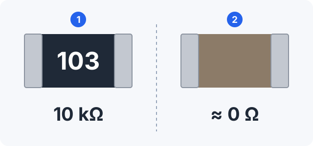
- Marking. Resistors 0603 and larger are almost always coded; chip inductors mostly are not.
- Colour. A resistor has a black or dark blue top over a white ceramic base; a multilayer inductor is usually the same colour all round, closer to a capacitor.
- Resistance. An inductor reads from a few hundredths of an ohm to a few ohms. A 0 Ω jumper (marked
0or000) and a ferrite bead also read near zero, though. - Position. In series with a supply line near a connector or IC — likely a bead; next to an antenna — an RF chip coil.
The look-alikes are covered in SMD resistor marking and SMD capacitor marking.
Testing an inductor
Ohmmeter
Finds only an open winding. A good power inductor reads from tens of milliohms to a few ohms (around 0.045 Ω for a Würth 10 µH part, up to 1.7 Ω for a Bourns 1000 µH part). Open circuit means a broken winding. Shorted turns are invisible to an ohmmeter: resistance changes by a fraction while inductance drops sharply.
LCR meter
Remove the part and measure at the datasheet test frequency (1 kHz or 100 kHz for power inductors). Inductance well below nominal, or a collapsed Q, points to shorted turns. In-circuit readings are unreliable because of parallel capacitors and ICs.
Visual check
A cracked ferrite, a darkened winding or a chipped corner means replace it, even if it beeps through.
Saturation current: never replace by inductance alone
A power inductor has a saturation current (Isat) — the current at which inductance has dropped by a stated percentage — and a rated current based on temperature rise. Manufacturers define them differently: Bourns uses a 25 % drop, Würth lists Isat at 10 % and at 30 %. A smaller 10 µH part in a switching supply will saturate, the switch current spikes and the MOSFET or controller fails. Match inductance, saturation current, size and shielding — ideally the exact part number from the datasheet. For the switching transistor itself, see SMD transistor marking.
Common mistakes
- Reading
100as 100 µH — it is 10 µH. - Fitting a smaller part with the same inductance — it overheats and saturates.
- Swapping shielded for unshielded “because the value is the same” — an open core in a dense layout couples noise into neighbouring circuits.
- Replacing a ferrite bead with a jumper: the board works, the filter is gone.
- Mistaking a chip inductor for a capacitor in the same case — an ohmmeter settles it at once, a capacitor reads open.
In short
- Three digits on an inductor are µH:
100= 10 µH,101= 100 µH. Ris the decimal point:4R7= 4.7 µH,R47= 0.47 µH.Nis the decimal point in nH — in part numbers, not on the body.- Small chip inductors and beads are usually unmarked; beads are rated in ohms at 100 MHz.
- An ohmmeter only finds open windings; shorted turns need an LCR meter.
- Replace by inductance, saturation current, size and shielding.
In ServiceCenterSoft an inductor taken from stock goes onto the repair estimate as a line item, and stock is kept as a movement log with quantities on hand and a minimum level, so parts that are running low show up straight away. More on that in spare parts tracking.
What does 100 mean on an SMD inductor?
10 µH. It reads like a resistor code, but in microhenries: “10” are the significant digits and the final “0” is the multiplier 10⁰, so no zeros are added. 101 is 100 µH, 470 is 47 µH.
How do I read 4R7 and R47 on an inductor?
R is the decimal point and the unit is microhenries: 4R7 = 4.7 µH, R47 = 0.47 µH. On a resistor the same code means ohms (4.7 Ω), so check the body: a power inductor is the square part next to the regulator IC.
Why is there no marking on a chip inductor?
Small multilayer and wirewound chip inductors (0402, 0603) are usually made without any print — there is no room, and the value lives only in the part number on the reel and in the BOM. Measure it with an LCR meter after removal, or look it up in the schematic or service manual.
How do I test an inductor with a multimeter?
On the resistance range a multimeter only finds an open winding: a good one reads from tens of milliohms to a few ohms. Shorted turns do not show up that way — you need an LCR meter, with the part removed, to compare inductance with the nominal value. A cracked ferrite or darkened winding is reason enough to replace it.
Can I replace an inductor with any part of the same inductance?
Only if saturation current, size and shielding match too. A smaller part with the same microhenries saturates in a switching supply, the switch current spikes and the transistor or controller fails. The safest route is the exact part number from the datasheet.
How is a ferrite bead different from an inductor?
A bead absorbs high-frequency noise and is rated in ohms of impedance at 100 MHz rather than in microhenries — Murata BLM18KG471, for example, is 470 Ω at 100 MHz. At DC it is nearly a short, so an ohmmeter reads close to zero. Do not replace it with a jumper: the filtering is lost.
See also
SMD Diode Marking: Cathode Band and Codes Like M7, A7, Z2
Which end of an SMD diode or LED is the cathode, why the print on the body is a manufacturer code rather than a part number, and how to identify a part from code, package and pin count. Verified examples M7, S4, A7, Z2, SMAJ, plus meter checks.
Read moreSMD Transistor Marking Codes: SOT-23, SOT-223, SC-70 and SOT-89
Why a SOT-23 carries a short code instead of a part number, how to identify the part from code and package, why manufacturers use different codes, SOT-23 and SOT-223 pinouts, multimeter checks.
Read moreSMD IC Marking: Pin 1, Part Code and Date Code
How to find pin 1 on an SMD IC and which way to count, what the lines on the package mean — logo, shortened part code, date code — how to spot a remarked part and test a chip on the board.
Read more