SMD Transistor Marking Codes: SOT-23, SOT-223, SC-70 and SOT-89
Why a SOT-23 carries a short code instead of a part number, how to identify the part from code and package, why manufacturers use different codes, SOT-23 and SOT-223 pinouts, multimeter checks.
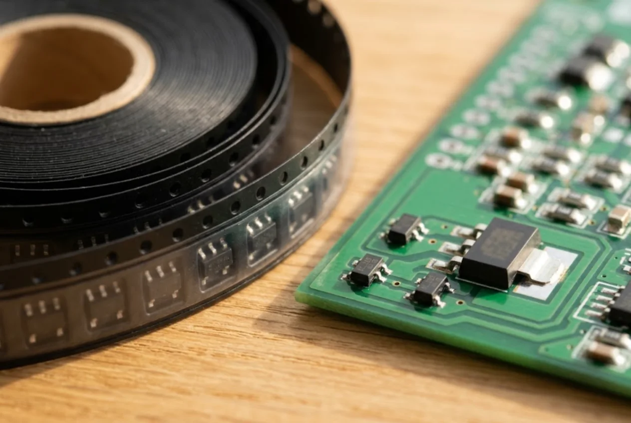
A small SMD transistor never says “BC847B” on top. It says 1F, or K1R, or SS. Resistor codes follow a standard, so 103 means 10 kΩ no matter who made the part. Transistor and small-IC codes do not: each manufacturer assigns its own. This page explains what the characters mean, how to get from a code to a datasheet, which pin is which, and how to test the part with a multimeter.
Packages you will meet
- SC-70 (also SOT-323): the smallest of the group, about 2.0 × 1.25 mm, three leads.
- SOT-23: the most common, about 2.9 × 1.3 mm, two leads on one side and one on the other. Five- and six-lead versions (SOT-23-5, SOT-23-6) usually hold ICs such as regulators and op-amps; see SMD IC marking.
- SOT-89: about 4.5 × 2.5 mm, three leads on one side, the middle one wider and joined to the pad under the body.
- SOT-223: 6.5 × 3.5 mm, three narrow leads at the bottom and a wide fourth lead (tab) at the top for heat.
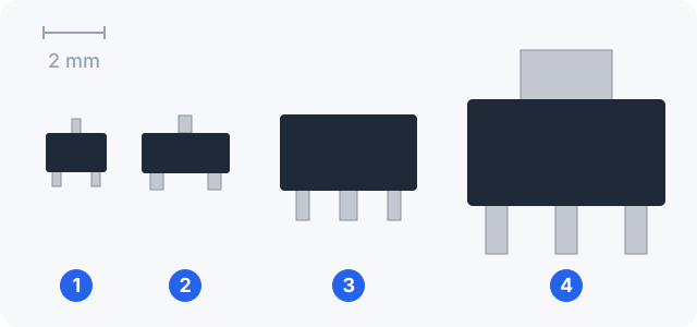
The package alone tells you little. A SOT-23 may contain a bipolar transistor, a MOSFET, a dual diode, a Zener or a voltage reference. Diodes in these packages are covered in SMD diode marking.
Why a code instead of a part number
There is room for three or four characters on a SOT-23, and a part number like MMBT3904 needs eight. So the maker prints a short device code, often followed by a date or factory character.
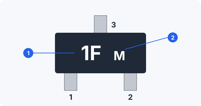
1F is onsemi’s BC847B), 2 — date character. Pins: 1 bottom left, 2 bottom right, 3 alone on the opposite side.What the extra characters mean is defined in each datasheet:
- onsemi uses
XXMG:XXis the device code,Ma date code,Gor a microdot marks a lead-free part. So1Fplus a letter is the code1Fplus a date. - Diodes Incorporated prints
XXXwithYMnext to it: year as a letter, then the month. - Philips (later NXP, now Nexperia), in the 2002 BC847 datasheet, used
1F*, where*is the factory:pfor Hong Kong,tfor Malaysia.
Lesson one: not every character is part of the code. Search for the full string and for the first two characters.
Same transistor, different codes
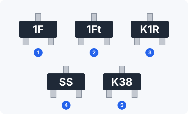
There is no common standard for these codes. The same device carries different codes depending on the manufacturer, straight from their own datasheets:
| Device | Type | onsemi | Diodes Inc. | Philips (2002) |
|---|---|---|---|---|
| BC847B | NPN, 45 V, 100 mA | 1F | K1R | 1F* |
| MMBT3904 | NPN, 40 V, 200 mA | 1AM | K1N | — |
| BSS138 | N-channel MOSFET, 50 V | SS | K38 | — |
A dash means we did not check it. It also works the other way: one code, several devices. Diodes marks BC846B, BC847B and BC848B (65, 45 and 30 V parts) all as K1R, and the A versions all as K1Q. onsemi uses 1F for BC847B in SOT-23 and for BC847BW in SC-70; only the package size tells them apart.
Gain groups: 1E, 1F, 1G
The A/B/C suffix of BC847 is the hFE (current gain) group, and the code follows it:
| Device | hFE at 2 mA | onsemi, Philips | Diodes |
|---|---|---|---|
| BC847A | 110–220 | 1E | K1Q |
| BC847B | 200–450 | 1F | K1R |
| BC847C | 420–800 | 1G | K1M |
How to identify a part from its code
- Read every character under magnification and write it down. Keep in mind the last one may be a date.
- Identify the package and lead count. Measure it: SC-70 and SOT-23 are easy to confuse by eye.
- Look at the circuit around it. A base resistor and a load suggest a switch; caps on input and output suggest a regulator; parts next to a connector are often protection diodes.
- Look up candidates in an SMD code book or online code database by code and package. Expect several devices from different makers.
- Open each candidate’s datasheet and check the marking table (Marking, Ordering Information) and the pinout.
- Confirm by measurement. If you have the service schematic of the unit, the part number there beats any code book.
SOT-23 pinout
Numbering is always the same: top view, two leads at the bottom — 1 on the left, 2 on the right — and the single lead opposite is 3. What sits on each pin depends on the device:
| Variant | 1 | 2 | 3 | Checked in |
|---|---|---|---|---|
| Bipolar, most common | base | emitter | collector | onsemi BC847, MMBT3904; Philips BC847 |
| MOSFET, most common | gate | source | drain | onsemi and Diodes BSS138 |
| Other bipolar | emitter | base | collector | onsemi SOT-23 outline, STYLE 7 |
| Other MOSFET | drain | source | gate | onsemi SOT-23 outline, STYLE 10 |
Base–emitter–collector is the usual layout, not a rule. onsemi’s SOT-23 package drawing alone lists more than twenty pin styles. Take the pinout from the datasheet of the exact part.
SOT-223 and SOT-89: the wide lead
The wide top lead of a SOT-223 (pin 4, or TAB) moves heat into the copper. In every example we checked it is connected to the middle pin 2, but what pin 2 does varies.
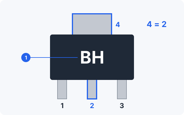
BH is onsemi’s BCP56). Tab 4 is tied to pin 2.| Device, package | 1 | 2 | 3 | 4 (TAB) |
|---|---|---|---|---|
| BCP56 (onsemi), SOT-223 | base | collector | emitter | collector |
| LM1117 (TI), NCP1117 (onsemi), SOT-223 | ADJ/GND | output | input | output |
| AZ1117C (Diodes), SOT-223, H option | ADJ/GND | output | input | output |
| AZ1117C (Diodes), SOT-223, H2 option | input | ADJ/GND | output | ADJ/GND |
The last two rows are the same chip in the same package with different pinouts. The tab is not necessarily ground — on a regulator it is often the output — and the copper under it may be live.
In SOT-89 the middle lead continues into the pad under the body. AZ1117C in SOT-89 also comes in two versions: R is 1 ADJ/GND, 2 output, 3 input; R2 is 1 ADJ/GND, 2 input, 3 output.
Testing with a multimeter
In diode-test mode the meter shows the forward voltage of a junction.
Bipolar transistor
On an NPN, red probe on the base, black on emitter, then collector: roughly 0.5–0.8 V each, open the other way. Collector to emitter is open both ways. A PNP is the mirror image. This tells you both the type and the base. Digital (pre-biased) transistors with built-in resistors read differently; that alone does not mean the part is bad.
MOSFET
- The gate shows no conduction to source or drain.
- Source to drain there is a body diode: on an N-channel part, red on source and black on drain reads about 0.4–0.8 V, the reverse is open.
- To switch it on, touch red to the gate and black to the source; the gate charges and drain–source now reads almost a short. Short gate to source with tweezers and it turns off. This works when the meter’s test voltage exceeds the gate threshold; the BSS138 datasheets give 0.5–1.5 V.
Gates are sensitive to static, so handle the part with tweezers. In-circuit readings are distorted by parallel parts; for a definite answer, remove the part with hot air first.
Common mistakes
- Replacing by code without a datasheet. At Diodes,
K1Ris three different transistors, and another maker may use the same code for something unrelated. - Reading the date as part of the code. onsemi marks BC846A as
1Aand MMBT3904 as1AM, each followed by a date letter. - Assuming the pinout. Base–emitter–collector is not guaranteed; a MOSFET in the same package is gate–source–drain, and other layouts exist.
- Guessing the package. SC-70 and SOT-23 parts with the same code differ in size and power rating.
- Treating the SOT-223 tab as ground. On a regulator it is often the output.
- Wrong gain group. BC847A instead of BC847C has several times less hFE.
In short
- Codes on SOT-23, SC-70, SOT-89 and SOT-223 are not standardised; each manufacturer sets its own.
- Search by code + package + lead count, then confirm in the candidate’s datasheet.
- The last character is often a date or factory mark.
- SOT-23 numbering is fixed (1 and 2 bottom, 3 top); pin functions are not.
- In the examples checked, the SOT-223 tab is tied to pin 2 — which is not necessarily ground.
- Test: bipolar junctions read 0.5–0.8 V; a MOSFET shows a drain–source body diode and turns on when the gate is charged.
Compare with resistors, where the code is standard: SMD resistor marking. In ServiceCenterSoft a part from stock is added as a line in the repair estimate, and stock is kept as a log with quantities on hand and a minimum level, so items running low show up in their own filter. More in spare parts accounting.
How do I identify a SOT-23 transistor from its marking code?
Write down every character, identify the package (SC-70, SOT-23, SOT-89, SOT-223) and the lead count, then look up candidates in an SMD code database by code and package. Open each candidate’s datasheet, compare the marking table and the pinout, and confirm with a multimeter. The last character is often a date or factory mark rather than part of the code.
Why does the same transistor have different marking codes?
There is no standard for SMD transistor codes; each manufacturer assigns its own. onsemi marks BC847B as 1F, Diodes Incorporated as K1R; the BSS138 MOSFET is SS and K38. It also works the other way: Diodes uses K1R for BC846B, BC847B and BC848B alike. So never replace a part by code alone without the datasheet.
What is the SOT-23 pinout: which pin is base, emitter and collector?
Numbering is fixed: top view, two leads at the bottom — 1 on the left, 2 on the right — and the single lead opposite is 3. Most bipolar transistors use 1 base, 2 emitter, 3 collector; most MOSFETs use 1 gate, 2 source, 3 drain. It is not a rule, though: other layouts exist, so take the pinout from the datasheet of the exact part.
What is the wide tab of a SOT-223 connected to?
In the datasheets we checked, the wide pin 4 is tied to the middle pin 2. What pin 2 is varies: on the BCP56 transistor it is the collector, on LM1117 and NCP1117 regulators it is the output. So the tab is not necessarily ground, and the copper under it may be live.
How do I test an SMD transistor with a multimeter?
Use diode-test mode. Bipolar: base–emitter and base–collector read roughly 0.5–0.8 V one way and open the other; collector–emitter is open both ways. MOSFET: the gate shows no conduction to anything, there is a body diode between source and drain, and charging the gate with the probe turns drain–source on. In circuit, neighbouring parts distort readings, so remove the part for a definite answer.
See also
SMD IC Marking: Pin 1, Part Code and Date Code
How to find pin 1 on an SMD IC and which way to count, what the lines on the package mean — logo, shortened part code, date code — how to spot a remarked part and test a chip on the board.
Read moreSMD Resistor Codes: How to Read 103, 4R7 and EIA-96 (01C)
How to read the code on an SMD resistor: 3- and 4-digit codes, R as the decimal point, EIA-96 with the full table, 0 Ω jumpers, case sizes 0201–2512 and in-circuit checks with a multimeter.
Read moreSMD Capacitor Markings: Tantalum Codes, Polarity and Ceramics
How to read SMD capacitor markings: capacitance codes in picofarads (107 = 100 µF), tantalum voltage letters, which side is positive, tantalum case sizes A–D and why ceramic chips carry no marking.
Read more