SMD Capacitor Markings: Tantalum Codes, Polarity and Ceramics
How to read SMD capacitor markings: capacitance codes in picofarads (107 = 100 µF), tantalum voltage letters, which side is positive, tantalum case sizes A–D and why ceramic chips carry no marking.
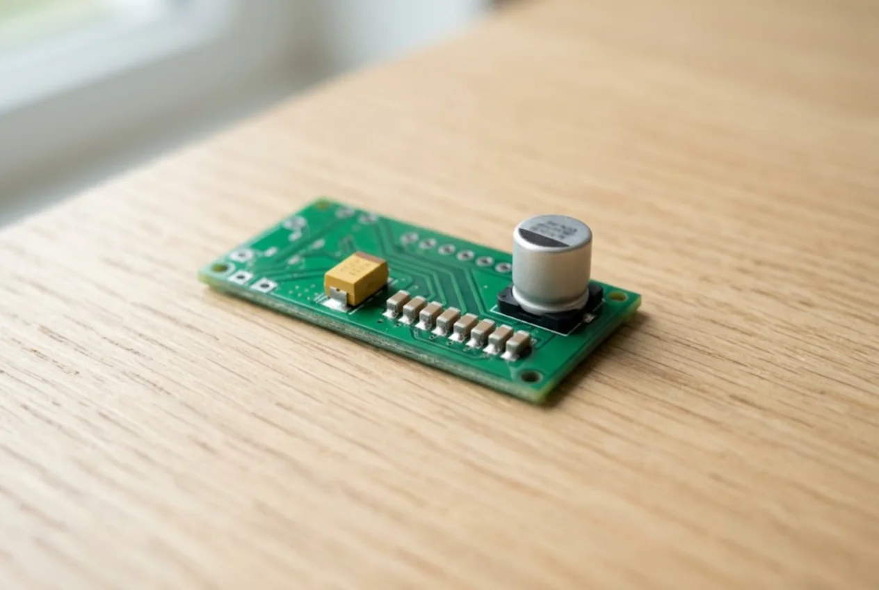
Three kinds of SMD capacitor turn up on a typical board, and each is marked differently. Multilayer ceramic chips (MLCCs), by far the most common, usually carry no marking at all. Tantalum capacitors, the yellow or black moulded blocks, show a capacitance code, a voltage letter and a polarity band. Aluminium SMD electrolytics, small cans on a plastic base, show the value in plain microfarads and a dark sector on the top. This page explains how to read each one, which end is positive and what to do when there is nothing printed.
Types and case sizes
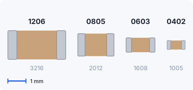
Multilayer ceramic capacitors (MLCC) are beige, brown or grey blocks with metal end caps. Their size is given as an imperial code (0402, 0603, 0805, 1206) or a metric one (1005, 1608, 2012, 3216), which is length and width in tenths of a millimetre. Watch out: a metric “0603” is the tiny imperial 0201, not the familiar 0603.
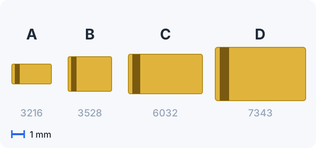
Tantalum capacitors sit in a moulded body with terminations at each end. The case is named by a letter, and for the common A, B, C and D cases KEMET and KYOCERA AVX use the same letters:
| Case | EIA metric | Imperial | Length × width, mm | Max. height, mm |
|---|---|---|---|---|
| A | 3216-18 | 1206 | 3.2 × 1.6 | 1.8 |
| B | 3528-21 | 1210 | 3.5 × 2.8 | 2.1 |
| C | 6032-28 | 2312 | 6.0 × 3.2 | 2.8 |
| D | 7343-31 | 2917 | 7.3 × 4.3 | 3.1 |
The number after the dash is the maximum height in tenths of a millimetre. Beyond D the letters diverge: the tall 7343-43 case is E at AVX and X at KEMET, and KEMET’s V is a low-profile 7343-20 while AVX’s V is a 7361-38. When ordering, go by the metric code rather than the letter.
Aluminium SMD electrolytics are a metal can on a black plastic base, with the leads coming out underneath. Their size is the can’s diameter and height in millimetres.
Ceramic capacitors: usually no marking
An unmarked MLCC is normal. KEMET’s datasheets state that its MLCCs are “normally supplied unmarked”, and at Vishay marking is an ordering option. Laser marking is applied only on request and every maker uses its own code. Older boards sometimes show a two-character code (a letter and a digit), but there is no common table for it, so do not try to guess a value from it.
To find the capacitance of a ceramic chip:
- check the schematic or boardview — the most reliable source;
- compare with a known-good identical board, or with an identical channel on the same board;
- remove the part and measure it with an LCR meter or a multimeter with a capacitance range.
Measuring on the board does not work: other capacitors in parallel add up. The voltage rating is not printed either, so a replacement should match the schematic or exceed it, use the same dielectric (C0G, X7R, X5R) and be no smaller in case size.
Tantalum: the capacitance code is in picofarads
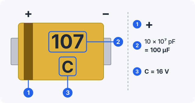
Tantalum capacitance uses a three-digit code in picofarads, built like an SMD resistor code: two significant digits followed by the number of zeros.
107= 10 × 10⁷ pF = 100,000,000 pF = 100 µF;106= 10 × 10⁶ pF = 10 µF;227= 22 × 10⁷ pF = 220 µF;475= 47 × 10⁵ pF = 4.7 µF.
A quick rule: a final 6 means single or tens of microfarads, a final 7 means hundreds.
Tantalum voltage letters
Small cases have no room for “16V”, so the rated voltage is printed as a single letter. The table lists the letters that KYOCERA AVX (TAJ series) and Vishay (293D series) decode identically:
| Letter | Rated voltage |
|---|---|
G | 4 V |
J | 6.3 V |
A | 10 V |
C | 16 V |
D | 20 V |
E | 25 V |
V | 35 V |
T | 50 V |
So 107 C is 100 µF at 16 V, 227 A is 220 µF at 10 V and 106 J is 10 µF at 6.3 V. Some series use additional letters below 4 V or above 50 V — check the series datasheet. Do not confuse the voltage letter with the case letter: an “A” next to the capacitance code means 10 V.
Larger cases often spell the voltage out. Vishay prints microfarads and volts (22 and 10 — 22 µF, 10 V); KEMET prints the picofarad code plus the voltage and its own ID letter (157 and 6K — 150 µF, 6.3 V, with 6.3 V shortened to “6”). Manufacturers also reserve the right to ship a higher voltage rating in the same case, so the part on the board may be rated higher than the parts list says.
Which side is positive on a tantalum capacitor
The band on a tantalum capacitor marks the positive (anode) end. KEMET, AVX and Vishay all mark it this way, and KEMET bodies may also have a bevelled edge on the positive side. The classic trap is the diode: on an SMD diode the band marks the cathode, the negative side (see SMD diode markings). On the same board the two bands mean opposite things.
Polymer tantalum capacitors, such as KEMET T520 or KYOCERA AVX TCJ, follow the same scheme: band at the positive end, picofarad code, voltage as a letter or a number.
Aluminium SMD electrolytics: plain microfarads, dark sector is negative
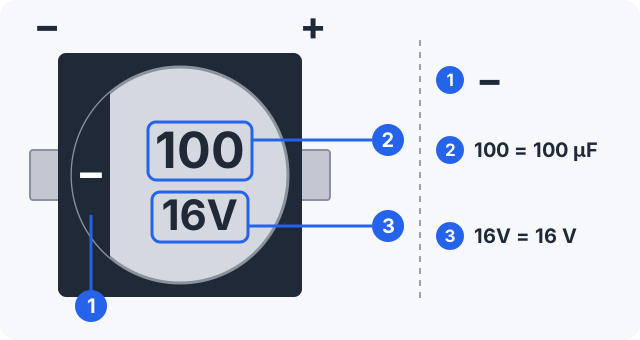
The top of an aluminium SMD electrolytic shows the capacitance as a plain number in microfarads, not a code: 100 means 100 µF. The voltage sits next to it. Nichicon prints it in volts (16V); Panasonic uses a letter together with the series name, so 100 and j FP means 100 µF, 6.3 V, FP series. At Panasonic 50 V is H, whereas on tantalum 50 V is T — do not mix the two schemes, and check the series datasheet when unsure.
The dark, filled sector on the top marks the negative terminal; positive is the opposite side.
Testing when the marking is missing or worn off
- Tantalum typically fails short: an ohmmeter across the supply rail reads a few ohms or less. Find the culprit by lifting parts one at a time, or by looking for the hot spot while a current-limited bench supply feeds a low voltage into the rail.
- Electrolytics lose capacitance and gain ESR. Visible signs are a domed top, leaked electrolyte and corrosion around the part. Use an ESR meter; for a precise reading, measure it removed.
- Ceramic chips fail short across the end caps, or crack and go open or intermittent. Measure capacitance only on a removed part.
- For a part with no readable marking, take the value from the schematic or boardview, from an identical good board or from an identical neighbouring channel.
Common mistakes
- Tantalum fitted backwards. Reverse polarity destroys it: it heats up, fails short and on a strong supply can catch fire. Check the band against the “+” on the board before powering up.
- Reading the band like a diode’s. On tantalum the band is positive; on a diode it is negative.
- Reading “107” as 107 µF. It is a picofarad code: 100 µF.
- Taking the voltage letter for the case size. “A” next to the code is 10 V.
- Replacing with a lower voltage. Use the same or higher; on supply rails give tantalum some margin.
- Keeping a domed electrolytic. A bulging top means replace, even if the capacitance still looks fine.
- Measuring in circuit. Parallel parts distort both capacitance and ESR readings.
Related pages: SMD resistor codes and SMD inductor markings — an 0805 inductor is easy to mistake for a ceramic capacitor.
In short
- Ceramic chips (MLCC) are usually unmarked — take the value from the schematic or measure a removed part.
- Tantalum: picofarad code (107 = 100 µF) plus a voltage letter (C = 16 V, A = 10 V).
- The band on tantalum is positive; on a diode it is negative.
- Electrolytics: plain microfarads; the dark sector is negative.
- Tantalum cases A, B, C, D = 3216, 3528, 6032, 7343; other letters vary by maker.
If you run your repairs in ServiceCenterSoft, a capacitor from stock goes into the repair estimate as a line and is deducted from stock. Stock is kept as a log of receipts and write-offs, and for parts you use a lot — say, 100 µF 16 V tantalums — you can set a minimum level so the item shows up under “running low”. More on spare parts tracking.
What does 107 mean on a tantalum capacitor?
It is the capacitance code in picofarads: two significant digits, then the number of zeros. 107 = 10 × 10⁷ pF = 100 µF. Likewise 106 = 10 µF, 227 = 220 µF and 475 = 4.7 µF. The letter next to it is the voltage: 107 C means 100 µF at 16 V.
Which side of a tantalum capacitor is positive?
The side with the band: on a tantalum capacitor the band marks the positive (anode) end. That is the opposite of a diode, where the band marks the cathode, the negative side. A tantalum fitted backwards heats up, fails short and on a strong supply can catch fire.
What do the letters A, C, E, V on a tantalum capacitor mean?
They are the rated voltage code: G = 4 V, J = 6.3 V, A = 10 V, C = 16 V, D = 20 V, E = 25 V, V = 35 V, T = 50 V (the same in KYOCERA AVX and Vishay datasheets). Do not confuse it with the case letter: an “A” next to the capacitance code means 10 V.
How do I find the value of an unmarked SMD capacitor?
Ceramic SMD capacitors are usually unmarked. Take the value from the schematic or boardview, from an identical good board or from an identical neighbouring channel. Otherwise remove the capacitor and measure it with an LCR meter or a multimeter with a capacitance range — on the board the meter reads parallel parts as well.
Which side of an SMD electrolytic capacitor is negative?
The side with the dark, filled sector on the top — that is the negative terminal. The capacitance is printed in plain microfarads: 100 means 100 µF. Next to it is the voltage, either in volts (16V) or as a maker’s letter code, which is worth checking in the series datasheet.
See also
SMD Inductor Marking: Codes 100, 4R7 and R47 Explained
How to read the code on an SMD power inductor or chip inductor: three digits in µH, R as the decimal point, N for nanohenries, ferrite beads rated in ohms. How to tell one from a resistor, how to test it and why inductance alone is not enough for a replacement.
Read moreSMD Diode Marking: Cathode Band and Codes Like M7, A7, Z2
Which end of an SMD diode or LED is the cathode, why the print on the body is a manufacturer code rather than a part number, and how to identify a part from code, package and pin count. Verified examples M7, S4, A7, Z2, SMAJ, plus meter checks.
Read moreSMD Transistor Marking Codes: SOT-23, SOT-223, SC-70 and SOT-89
Why a SOT-23 carries a short code instead of a part number, how to identify the part from code and package, why manufacturers use different codes, SOT-23 and SOT-223 pinouts, multimeter checks.
Read more