SMD Resistor Codes: How to Read 103, 4R7 and EIA-96 (01C)
How to read the code on an SMD resistor: 3- and 4-digit codes, R as the decimal point, EIA-96 with the full table, 0 Ω jumpers, case sizes 0201–2512 and in-circuit checks with a multimeter.
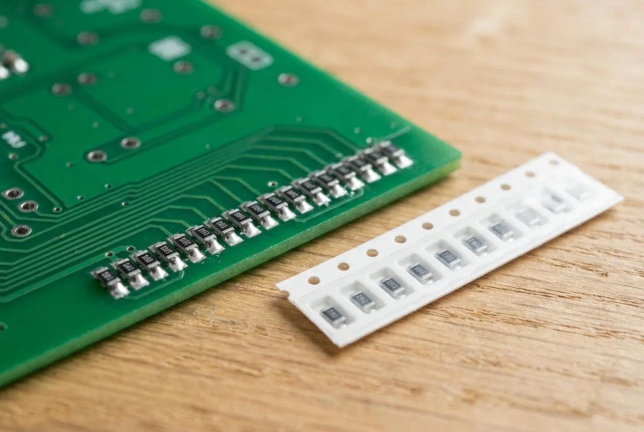
Chip resistors are the most common part on almost any board you open. Instead of colour bands they carry a short code of three or four characters — and on the smallest cases, nothing at all. This page walks through the standard marking systems (IEC 60062 and EIA) with worked examples, gives the complete EIA-96 table, and explains what to do when the marking is gone. Capacitors follow different rules; see SMD capacitor markings.
Case sizes and typical power
The case size is four digits: length and width. Most catalogues use inch codes, so 0805 means 0.08 × 0.05 in. Some use metric codes, and that is where mistakes happen: metric 0603 is the tiny inch 0201 (0.6 × 0.3 mm), while the familiar inch 0603 is metric 1608. Check which system a distributor uses before you order.
| Inch | Metric | Size, mm | Typical power |
|---|---|---|---|
| 0201 | 0603 | 0.6 × 0.3 | 1/20 W |
| 0402 | 1005 | 1.0 × 0.5 | 1/16 W |
| 0603 | 1608 | 1.6 × 0.8 | 1/10 W |
| 0805 | 2012 | 2.0 × 1.25 | 1/8 W |
| 1206 | 3216 | 3.1 × 1.55 | 1/4 W |
| 2010 | 5025 | 5.0 × 2.5 | 1/2 W and up |
| 2512 | 6432 | 6.3 × 3.2 | 1 W |
These are typical ratings at 70 °C for standard thick-film parts (Bourns CR and Yageo RC datasheets). High-power series exist in the same cases, so always take the figure from the datasheet of the actual part. Don't drop a smaller case into a larger footprint just because the value matches — it dissipates less heat.
0201 and 0402 parts are usually unmarked. 0603 parts mostly carry three characters, 0805 and larger three or four.
Three-digit code: 103, 472, 330
Used on 5 % resistors (E24 series). The first two digits are significant, the third is the number of zeros to add — the power of ten. The result is in ohms.
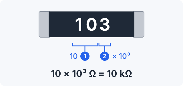
103= 10 × 10³ = 10 kΩ472= 47 × 10² = 4.7 kΩ101= 100 Ω224= 220 kΩ105= 1 MΩ330= 33 Ω, not 330 Ω — a trailing zero means “add no zeros”.
Some makers put a short bar under a three-digit code on 0603 parts to mark a 1 % E24 value (Yageo does this). Read the value the usual way.
Four-digit code: 4702, 1002, 3160
Precision resistors (1 % and better) need three significant digits, so the code grows to four characters: three significant digits plus the number of zeros.
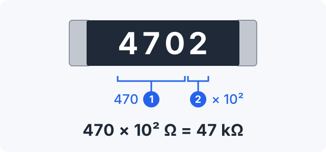
4702= 470 × 10² = 47 kΩ1002= 10 kΩ1001= 1 kΩ4422= 44.2 kΩ3160= 316 Ω
Watch out: 1000 is 100 Ω, and 1002 (10 kΩ) is not the same part as 102 (1 kΩ).
R as the decimal point
Values below 10 Ω (below 100 Ω in the four-digit code) use the letter R where the decimal point would be. There is no multiplier; what you read is the value in ohms.
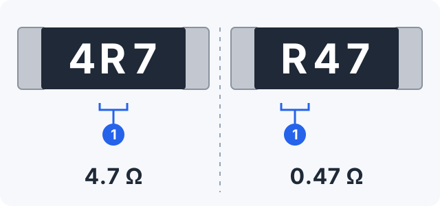
4R7= 4.7 Ω,2R2= 2.2 Ω,1R0= 1 ΩR47= 0.47 Ω,R10= 0.1 Ω31R6= 31.6 Ω
Milliohm current-sense resistors
Shunts in power supplies, chargers and battery management boards are in the milliohm range. They use the same R (R020 = 20 mΩ) or, in some series, a lower-case m as the decimal point: 1m5 = 1.5 mΩ (Yageo PR and PA series). If a shunt carries a code you don't recognise, look up the series datasheet rather than guessing.
EIA-96: two digits and a letter (01C, 68X)
Four characters don't fit on an 0603 case, so 1 % E96 values there use the EIA-96 code. The two digits are not the value but its index in the E96 series (01 to 96); the letter is the multiplier. Look the index up in the table below and multiply.
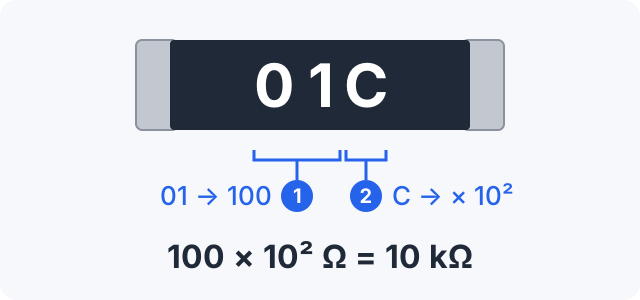
01C= 100 × 10² = 10 kΩ10C= 124 × 10² = 12.4 kΩ09B= 121 × 10 = 1.21 kΩ88A= 806 Ω68X= 499 × 0.1 = 49.9 Ω
Multiplier letters
| Letter | Multiplier | Letter | Multiplier |
|---|---|---|---|
Z | × 0.001 | C | × 100 |
Y | × 0.01 | D | × 1,000 |
X | × 0.1 | E | × 10,000 |
A | × 1 | F | × 100,000 |
B | × 10 |
These letters agree across manufacturer datasheets and reference charts. R, S and H do not: some tables give R = × 0.01 and S = × 0.1, others the reverse, and H appears both as × 10 and as × 10⁷. If you meet one of those, measure the part or find the datasheet. Also note that F here is a multiplier, not the 1 % tolerance letter used in part numbers.
EIA-96 code table
| Code | Value | Code | Value | Code | Value | Code | Value |
|---|---|---|---|---|---|---|---|
01 | 100 | 25 | 178 | 49 | 316 | 73 | 562 |
02 | 102 | 26 | 182 | 50 | 324 | 74 | 576 |
03 | 105 | 27 | 187 | 51 | 332 | 75 | 590 |
04 | 107 | 28 | 191 | 52 | 340 | 76 | 604 |
05 | 110 | 29 | 196 | 53 | 348 | 77 | 619 |
06 | 113 | 30 | 200 | 54 | 357 | 78 | 634 |
07 | 115 | 31 | 205 | 55 | 365 | 79 | 649 |
08 | 118 | 32 | 210 | 56 | 374 | 80 | 665 |
09 | 121 | 33 | 215 | 57 | 383 | 81 | 681 |
10 | 124 | 34 | 221 | 58 | 392 | 82 | 698 |
11 | 127 | 35 | 226 | 59 | 402 | 83 | 715 |
12 | 130 | 36 | 232 | 60 | 412 | 84 | 732 |
13 | 133 | 37 | 237 | 61 | 422 | 85 | 750 |
14 | 137 | 38 | 243 | 62 | 432 | 86 | 768 |
15 | 140 | 39 | 249 | 63 | 442 | 87 | 787 |
16 | 143 | 40 | 255 | 64 | 453 | 88 | 806 |
17 | 147 | 41 | 261 | 65 | 464 | 89 | 825 |
18 | 150 | 42 | 267 | 66 | 475 | 90 | 845 |
19 | 154 | 43 | 274 | 67 | 487 | 91 | 866 |
20 | 158 | 44 | 280 | 68 | 499 | 92 | 887 |
21 | 162 | 45 | 287 | 69 | 511 | 93 | 909 |
22 | 165 | 46 | 294 | 70 | 523 | 94 | 931 |
23 | 169 | 47 | 301 | 71 | 536 | 95 | 953 |
24 | 174 | 48 | 309 | 72 | 549 | 96 | 976 |
Zero-ohm jumpers: 0 or 000
A resistor marked 0 (on some parts 000 or 0000, depending on the case) is a jumper — a conductor in a resistor package, used to hop over a trace or to select a circuit option at assembly. Its resistance is not exactly zero but up to a few tens of milliohms (max. 50 mΩ for the Bourns CR series), and it has a current rating in the datasheet. Replace it with the same part. If one has burnt, find the short downstream first, or the new one will go the same way.
Resistor or inductor?
A dark block marked 4R7, 100 or 101 may be an SMD power inductor. On those the code is inductance in microhenries, read by the same rule: 4R7 = 4.7 µH, 100 = 10 µH, 101 = 100 µH (TDK, Würth Elektronik, Jauch). Ways to tell them apart:
- Look: a resistor is flat, with a white ceramic underside and metal end caps; an inductor is thicker, often square, made of grey or black ferrite, sometimes with the winding visible.
- Position: next to a switching regulator IC and its output capacitors, it is most likely an inductor.
- Ohmmeter: a 4.7 µH inductor reads close to zero, a
4R7resistor about 4.7 Ω.
More on this in SMD inductor markings.
Checking a resistor on the board
- Power the board down and discharge the large capacitors.
- Measure in circuit. Parallel paths can only lower the reading, so a value clearly above nominal — or an open circuit — means the resistor is bad.
- A reading below nominal proves nothing yet: other parts, IC junctions or capacitors charging from the meter may sit in parallel. Swap the probes; if the number changes, there is a semiconductor in parallel.
- To be sure, lift one end and measure again.
- For low values, short the probes first and subtract the lead resistance. A milliohm shunt is beyond a normal multimeter — you need a four-wire (Kelvin) measurement.
When there is no marking (0402 and smaller) or it has burnt off, take the value from the schematic or boardview, from an identical working board, or from an identical channel on the same board, and measure the removed part on its own.
Common mistakes
- Reading
330as 330 Ω — it is 33 Ω. - Mixing up
4R7(4.7 Ω),470(47 Ω) and471(470 Ω). - Reading an EIA-96 code as a plain number:
01Cis 10 kΩ. Two digits and a letter always mean the table. - Confusing inch and metric case codes when ordering.
- Fitting a smaller case than the original — it may not handle the power.
- Replacing a resistor only because it “reads low” in circuit without checking what is in parallel.
- Taking an inductor for a resistor, or the other way round.
In short
- Three digits: two significant digits plus the number of zeros —
103= 10 kΩ. - Four digits: three significant digits plus the number of zeros —
4702= 47 kΩ. Ris the decimal point:4R7= 4.7 Ω; on shuntsmis the decimal point in milliohms.- Two digits and a letter — EIA-96: table value × multiplier,
01C= 10 kΩ. 0or000is a jumper.- In circuit a resistor can read low, but never high.
If you track repairs in ServiceCenterSoft, a resistor taken from stock goes onto the repair estimate as a line and comes off the stock balance. Stock is kept as a journal of receipts and write-offs, and for parts you use a lot you can set a minimum quantity, so they show up under “running low”. See spare parts tracking.
What does 103 mean on an SMD resistor?
It is the three-digit code: the first two digits are significant, the third is the number of zeros. 103 = 10 followed by three zeros = 10,000 Ω = 10 kΩ. Likewise 472 = 4.7 kΩ, 101 = 100 Ω, and 330 is 33 Ω, because a trailing zero means no zeros are added.
How do I read 4R7 or R47 on a resistor?
R marks the decimal point and there is no multiplier: 4R7 = 4.7 Ω, R47 = 0.47 Ω, 2R2 = 2.2 Ω. Power inductors use the same code in microhenries (4R7 = 4.7 µH), so check the body and measure — an inductor reads close to zero ohms.
What does a code like 01C or 68X mean?
That is the EIA-96 code used on 1 % resistors in 0603 cases. The two digits are an index into the E96 series, which you convert with a table (01 → 100, 68 → 499); the letter is the multiplier (X = 0.1, A = 1, B = 10, C = 100, D = 1,000). So 01C = 100 × 100 = 10 kΩ and 68X = 49.9 Ω.
What is a resistor marked 0 or 000?
It is a zero-ohm jumper — a conductor in a resistor package. Its resistance is up to a few tens of milliohms and its current rating is in the datasheet. If one has burnt, find the short behind it first, then fit the same part.
Why does my meter read lower than the resistor’s marking in circuit?
Other parts, IC junctions and capacitors sit in parallel and pull the reading down. Parallel paths can never make it read higher, so a value above nominal or an open circuit means the resistor is faulty. To be certain, lift one end and measure again.
The SMD resistor has no marking — how do I find its value?
0201 and 0402 parts are usually unmarked. Take the value from the schematic or boardview, from an identical working board, or from a matching channel on the same board. Measure the removed part on its own, since in-circuit readings can be low.
See also
SMD Capacitor Markings: Tantalum Codes, Polarity and Ceramics
How to read SMD capacitor markings: capacitance codes in picofarads (107 = 100 µF), tantalum voltage letters, which side is positive, tantalum case sizes A–D and why ceramic chips carry no marking.
Read moreSMD Inductor Marking: Codes 100, 4R7 and R47 Explained
How to read the code on an SMD power inductor or chip inductor: three digits in µH, R as the decimal point, N for nanohenries, ferrite beads rated in ohms. How to tell one from a resistor, how to test it and why inductance alone is not enough for a replacement.
Read moreSMD Diode Marking: Cathode Band and Codes Like M7, A7, Z2
Which end of an SMD diode or LED is the cathode, why the print on the body is a manufacturer code rather than a part number, and how to identify a part from code, package and pin count. Verified examples M7, S4, A7, Z2, SMAJ, plus meter checks.
Read moreSMD Transistor Marking Codes: SOT-23, SOT-223, SC-70 and SOT-89
Why a SOT-23 carries a short code instead of a part number, how to identify the part from code and package, why manufacturers use different codes, SOT-23 and SOT-223 pinouts, multimeter checks.
Read moreSMD IC Marking: Pin 1, Part Code and Date Code
How to find pin 1 on an SMD IC and which way to count, what the lines on the package mean — logo, shortened part code, date code — how to spot a remarked part and test a chip on the board.
Read more